First Order Logic in AI
Table of Content:
- What is knowledge engineering?
- The knowledge-engineering process
- Identify the task.
- Assemble the relevant knowledge.
- Decide on vocabulary.
- Encode general knowledge about the domain.
Content Highlight:
Knowledge Engineering: This process involves constructing a knowledge base in first-order logic. A knowledge engineer investigates a domain, identifies important concepts, and creates a formal representation. For illustration, we explore the process in the context of an electronic circuit domain, specifically a one-bit full adder. The knowledge-engineering process includes identifying the task, such as functional and structural analysis; assembling relevant knowledge about digital circuits; deciding on vocabulary to represent components like circuits, terminals, signals, and gates; and encoding general knowledge about the domain by establishing rules for signal values, types of gates, and their behaviors.
What is knowledge engineering?
Knowledge engineering is the process of constructing a knowledge base in first-order logic. A knowledge engineer investigates a particular domain, identifies important concepts within that domain, and creates a formal representation of these objects.
To illustrate, we will explore the knowledge engineering process in the context of an electronic circuit domain, a field with which many are already familiar. This approach is particularly effective for developing specialized knowledge bases.
The knowledge-engineering process:
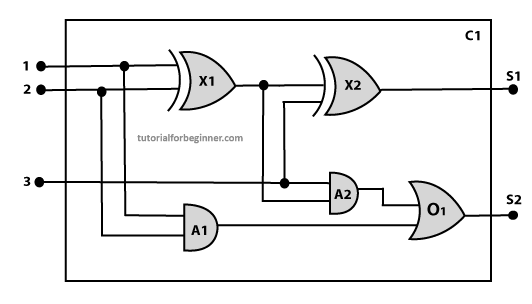
Below are the main steps of the knowledge-engineering process. By following these steps, we will develop a knowledge base that will enable us to reason about a digital circuit, specifically a one-bit full adder, as outlined below:
1. Identify the task:
Identify the task: The first step in the knowledge-engineering process is to identify the specific task at hand. For a digital circuit, particularly a one-bit full adder, this involves various reasoning tasks:
Level 1: Functional Analysis:
- Does the circuit add properly?
- What will be the output of gate A2 if all inputs are high?
Level 2: Structural Analysis:
- Which gate is connected to the first input terminal?
- Does the circuit have any feedback loops?
By identifying these tasks, we can systematically develop a knowledge base that enables us to reason about both the functionality and structure of the digital circuit.
2. Assemble the relevant knowledge:
Assemble the relevant knowledge: In the second step, we gather the essential knowledge needed for understanding digital circuits. For a digital circuit, the following knowledge is crucial:
- Logic circuits are composed of wires and gates.
- Signal flow: Signals travel through wires to the input terminals of gates, and each gate produces a corresponding output that flows further through the circuit.
- In this logic circuit, there are four types of gates used: AND, OR, XOR, and NOT.
- All these gates have one output terminal and two input terminals, except the NOT gate, which has one input terminal.
By assembling this knowledge, we can accurately describe and analyze the behavior and structure of the digital circuit.
3. Decide on vocabulary:
Decide on vocabulary: The next step in the knowledge-engineering process is to select appropriate functions, predicates, and constants to represent the components of our circuits, terminals, signals, and gates.
First, we need to distinguish the gates from each other and other objects. Each gate is represented as an object with a specific name, such as Gate(X1). The functionality of each gate is determined by its type, represented as constants like AND, OR, XOR, or NOT. Circuits are identified by the predicate Circuit(C1).
Terminals are represented using the predicate Terminal(x).
For gate inputs, we use the function In(1, X1) to denote the first input terminal of a gate, and Out(1, X1) for the output terminal.
The function Arity(c, i, j) indicates that circuit c has i input terminals and j output terminals.
The connectivity between gates is represented by the predicate Connect(Out(1, X1), In(1, X1)).
Lastly, we use a unary predicate On(t) to indicate that the signal at terminal t is active.
4. Encode general knowledge about the domain:
General Knowledge Encoding Rules:
Encode the general knowledge: To represent the general knowledge about the logic circuit, we need to establish some key rules:
1. Same signal for connected terminals:
If two terminals are connected, they have the same input signal:
∀ t1, t2 Terminal(t1) ∧ Terminal(t2) ∧ Connect(t1, t2) → Signal(t1) = Signal(t2).
2. Signal value at terminals:
The signal at every terminal will be either 0 or 1:
∀ t Terminal(t) → Signal(t) = 1 ∨ Signal(t) = 0.
3. Commutative Connect predicate:
Connect predicates are commutative:
∀ t1, t2 Connect(t1, t2) → Connect(t2, t1).
4. Types of gates:
Representation of types of gates:
∀ g Gate(g) ∧ r = Type(g) → r = OR ∨ r = AND ∨ r = XOR ∨ r = NOT.
5. Output of AND gate:
The output of an AND gate will be zero if and only if any of its inputs is zero:
∀ g Gate(g) ∧ Type(g) = AND → Signal(Out(1, g)) = 0 ⇔ ∃n Signal(In(n, g)) = 0.
6. Output of OR gate:
The output of an OR gate is 1 if and only if any of its inputs is 1:
∀ g Gate(g) ∧ Type(g) = OR → Signal(Out(1, g)) = 1 ⇔ ∃n Signal(In(n, g)) = 1.
7. Output of XOR gate:
The output of an XOR gate is 1 if and only if its inputs are different:
∀ g Gate(g) ∧ Type(g) = XOR → Signal(Out(1, g)) = 1 ⇔ Signal(In(1, g)) ≠ Signal(In(2, g)).
8. Output of NOT gate:
The output of a NOT gate is the inverse of its input:
∀ g Gate(g) ∧ Type(g) = NOT → Signal(In(1, g)) ≠ Signal(Out(1, g)).
9. Gate arity:
All gates in the circuit have two inputs and one output (except the NOT gate):
∀ g Gate(g) ∧ Type(g) = NOT → Arity(g, 1, 1).

∀ g Gate(g) ∧ r = Type(g) ∧ (r = AND ∨ r = OR ∨ r = XOR) → Arity(g, 2, 1).
10. Gates as circuits:
All gates are logic circuits:
∀ g Gate(g) → Circuit(g).